SoRoCAD Soft Robotic Actuator Design & Simulation Tool
- Anke Brocker
- May 4, 2023
- 2 min read
Updated: Sep 22, 2025
Difficulty: Easy
Duration: 30 min design; 5 h fabrication

Introduction
SoRoCAD is a tool for soft robotics design. It exposes design parameters in its UI and supports previewing the soft actuator's behavior by simulating the final actuation during the design phase. The following tutorial gives an example of how to design a silicone actuator using SoRoCAD that is ready for fabrication.
See our SoRoCAD paper: https://dl.acm.org/doi/abs/10.1145/3491101.3519770
Prerequisite & Background topics
Designing Soft Robots that move the way you would like them to move is hard. Basic physical rules apply here: e.g. for pneumatic actuation - air always pushes in the way of least resistance, i.e. the thinner wall gets pushed out. The simulation in the tool is a key fact as it gives you a chance to see what movement you designed robot will do after fabricating it (not 100% accurate in terms of angle of the movement but direction of movement is correct).
Materials & Equipment
• SoRoCAD (runs on Mac)
• 3D Printer
• Silicone
• Molding & Casting area
Interface Overview

There is an Exterior-geometry design window featuring:
(a) Viewport for the actuator;
(b) Three step design pipeline -
Channel, Exterior, Mould;
(c) Actuator control parameters;
(d) Run a Simulation button;
(e) Animated simulation preview.

A simulation window features:
(f) Viewport for the simulation;
(g) Simulation timestamps.
The actuator design process has a 3-step design pipeline, with a tab for each step:
Air Channels design
Silicone Exterior design;
Mold design
Air Channels

The tool offers 6 air channel types that can be stacked as blocks next to each other. Dimension, position, and rotation can be set for each channel.
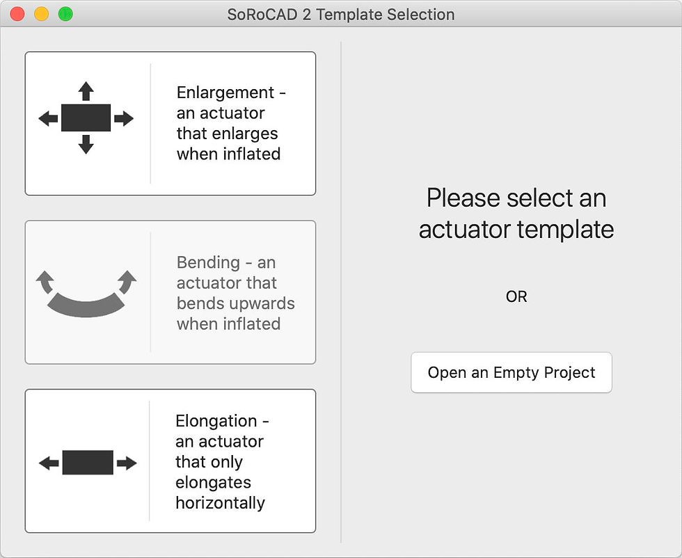
The software also provides users with templates, making the design process much simpler compared to when starting from scratch.
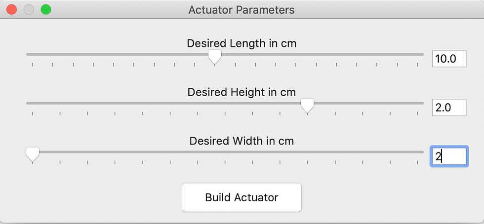
Length, Width, and Height can be set for the actuator, in centimeters, and the tool then builds the actuator.
Silicone Exterior
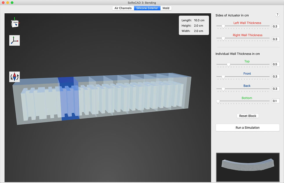
The software allows you to choose the following exterior parameters:
Actuator wall thickness
Left Wall / Right Wall
Individual Block Wall Thickness
Top / Front / Back / Bottom
The lower right corner shows an animation of the actuator behavior for the specified parameters.

When you press "Run a Simulation", a small window will appear asking you to specify the parameters:
Shore value
Pressure
Lower shore value corresponds to a softer and more flexible actuator.

When the simulation is started, you can step through the timestamps to examine the movement. Keep in mind that the simulation only approximates the real behavior and may not match it exactly.
Mold

The software can generate a 2-part mold for casting the actuator. You can specify the parameters:
Heigh of the split line
Side / Bottom thicknesses
The mold can be saved as STL.
Note that the mold is very primitive, with no tabs, vents, or other special features to latch the two pieces.
Fabrication

Going Further
What changes or new features would you add to the software?
Are there other design tools with similar capabilities and minimal learning curve?
Comments