Make Origami-Based Chamber Actuator

Difficulty: Easy
Duration: 60 min
Materials
• Clear plastic bag (thick)
• Clear plastic sheet
• Silicone tube 2mm ID
• Kapton tape or Masking tape
• Double-sided thin tape (3M 9495LE 300LSE)
• Alcohol wipes
Equipment
• Computer
• Printer
• 3D printer
• Heat sealer
• Scissors
• Permanent Marker
• FlowIO device
Heat Sealing Tips & Practice

1. Heat Sealer Operation
Depending on the brand and model, your heat sealer will have either a knob or buttons that let you control for how long heat is applied. You can only control time, but not temperature.
The heating element is on the bottom side,

and it activates when you push the lever arm down. It deactivates when the set time elapses or when you lift up the lever arm, whichever occurs first.

2. Identifying suitable timing setting
Before working on a project, we must first determine optimal settings for a good seal via experimentation on several test pieces.
Try sealing a 2-layer test piece at the lowest time available. Place your sample onto the machine then push and hold the lever arm down until the light turns off.

Wait a few seconds for cool off, then remove the test piece. If it did not seal, increase the time slightly and repeat this step using a new test piece. Your first goal is to find the minimum time required for achieving the weakest seal. It is important that you first do a very weak seal. Don't aim directly for a perfect seal yet.

3. Check tensile strength of seal-line
Try ripping apart the test piece you sealed. You should be able to separate it.
It is very important that you actually do this imperfect seal, to get a feel / intuition for the force needed break the seal for your specific material at each timing setting.
Increase the timing slightly and repeat this process on a new test piece until you are no longer able to break the seal line.
4. Inspect the seal-line for defects
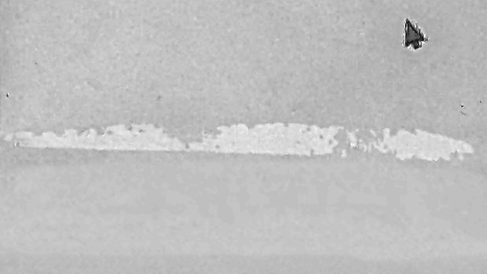
Even a strong seal has defects, which can result in air leaks. Place your test piece about 5cm away form a computer screen with a clear white background and take a photo of it. In post, increase contrast and apply other adjustments to would make the seal line pop so you can see defects clearly.

Increase the timing slightly and repeat this process on a new test piece until you start having a seal line without defects. Remember the timing you use!

5. Using a roller for smoother finish
Achieving a defect-free seal line often introduces the problem of shrinkage, making the surface look uneven and rough. We can mitigate this by using a roller over the work piece while it is still hot, immediately after lifting the lever arm. Do it rapidly at least 10-15 times with moderate downward force.

6. Sealing 3 stacked layers
Try sealing 3 layers. Did you notice that, even with longer time, the upper seal is weaker than the lower? That's because only the bottom of the 3 layers is heated directly.
Visual inspection is almost useless for 3 layers, because you only see the superposition of the two seal lines.

How can you make a 3-layer seal better? You can flip the work piece upside down and seal it again from the opposite side. And if you forgot which side was top and which was bottom during, you can just feel it by touch; the bottom side will feel more course.

7. Sealing N stacked layers
How many layers can you reasonably seal?

8. Leaving air channels unsealed
When making soft actuators, we may want to leave some gaps in the seal-line for air / fluid to flow through.

This can be achieved by masking the air channels regions with tape so that they don't get heated. When applying tape to the workpiece, it is critical that you place it on the side that would be on the BOTTOM during heat sealing, as it would have no effect if the tape is placed on the top.

Alternatively, you can place the tape on the heating element of the heat sealer itself, and then simply position your work piece over the tape as needed.
Careful! Test how many layers of tape you need. Too thin will seal the air channel. But too thick will not give a good seal around it. You must do a test to determine layer count.

9. Determine the offset of your sealer
Draw a straight line over a test piece and try sealing directly over the that straight line. Upon looking at the result, you will be surprised to see that seal line is offset from the line you drew! Carefully note how much that offset is and on which side.

Try this step a few more times until you are consistently able to make the seal line exactly match with your drawn line.
Actuator Fabrication Instructions

1. 3D Print a few Luer Fittings.
These fittings serve as the interface between your tube and actuator. They are tiny and must be printed on a resin printer.
(If you only have a basic FDM 3D printer, you can try scaling up the file to make it suitable for printing in your machine.)
2. Print an actuator stencil
Open the stencils PDF below and print it on a regular paper(A4 recommended). It includes stencil template for cutting and folding for this actuator.

3. Peel off protective film (from both sides)
Remove the protective film from both sides of the acrylic sheet.

4. Cut the panels and chamfer the corners.
Tape the cutting stencil template directly to the plastic sheet so it cannot shift. If it's possible, align plasic sheet's corner to the corner of the template.

Keep the complete paper template in place while cutting. Chamfer every panel corner by approximately 1 mm. Snip off the sharp tip of each corner and remove any sharp projections. Untrimmed corners can puncture the film.

5. Attach the panels and Marks.
Place the folding stencil template beneath the film and secure both with tape so they cannot shift relative to each other. Leave film beyond the dashed sealing lines for sealing and trimming.
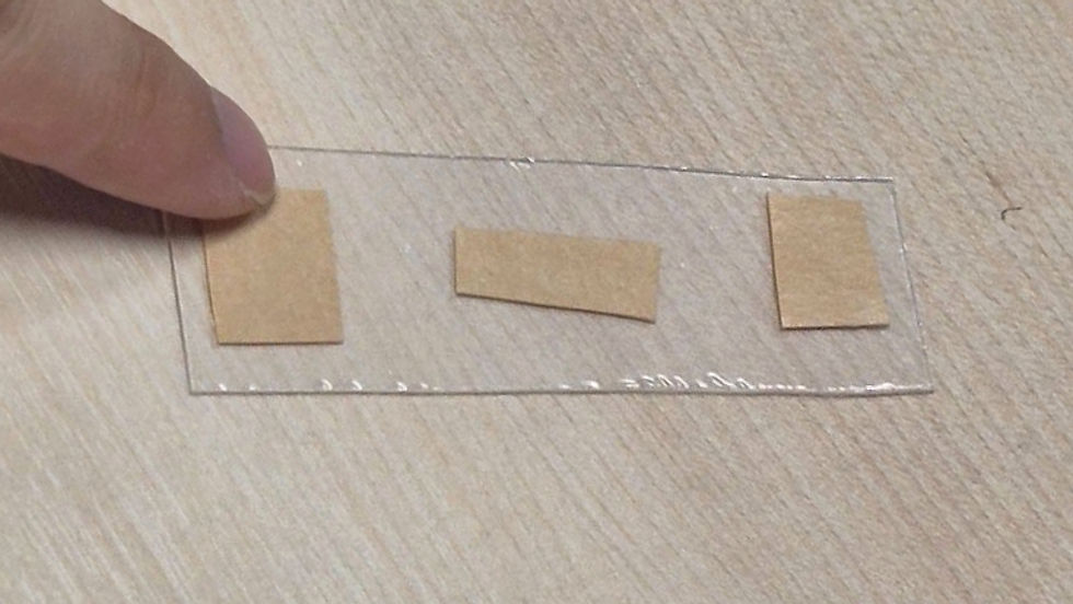
Apply double-sided tape to one face of each panel. Remove the exposed release liner when you are ready to attach that panel to the film.

Align each panel with its outline on the template and press it onto the film. Follow the Large–Small–Small–Large–Small–Small order and preserve the gaps shown on your printed folding template (4 mm in the supplied files).

Use a marker to trace all dashed sealing lines and the three solid fold lines onto the film. Keep the solid and dashed marks distinguishable.
Trace the circular inlet mark as well. Check that all marks have been transferred, then remove the film assembly from the template.

6. Fold the film.
Fold along the second marked solid fold line from the left, between the two Large–Small–Small groups. Fold the panel-covered faces toward each other for an internal skeleton.

Bring the two halves together and align the two outer vertical dashed sealing lines so they overlap. Keep the panels and film flat at the intended seam.

For easier handling, trim film outside the overlapping dashed lines, leaving a small margin beyond the intended seam. Keep the film needed for the two end seals.

7. Seal the aligned sealing line
Seal along the overlapping dashed lines to make the first seam. Refer to Heat Sealing Tips & Practice and use the setting appropriate for your film and layer stack.

Immediately after sealing finishes, roll the roller over the seal while the material and the bed are still very hot to prevent shrinkage. Roll it rapidly at least 10-15 times with moderate downward force.

Trim the remaining excess film outside the finished seam. Do not cut into the seal. Leave both ends open for attaching the air inlet and folding the sidewalls.

7. Attach the inlet and open the air passage.
Apply double-sided tape to the underside of the Luer Fitting(inlet). Trim any tape projecting beyond its circular base, following the edge of the base.

Align the inlet base with the circle marked on the film. Attach it to the outside of the film. Reach inside the open chamber and press the film firmly against the base to secure the bond.

From inside the chamber, use the tip of scissors or another pointed tool to pierce the film through the inlet opening. Open the air passage without tearing the surrounding film or puncturing the opposite layer.

8. Fold the sidewalls inward.
Lift the panels apart to open the chamber into a rectangular tube. The two large panels form the top and bottom surfaces.

Fold inward along the remaining marked solid fold lines, one between each pair of small panels. Viewed through an open end, the two sidewalls should form > < shapes.

Bring the two large panels together while keeping both sidewalls folded inward. Flatten the end regions and align the paired dashed sealing lines at each end.

9. Seal both ends and trim.
Keep the inward sidewall folds in place and seal along the overlapping dashed lines at one end. Repeat at the other end. Refer to heat-sealer guide for sealing the folded layers.

Trim the film outside both finished end seams, leaving the seals intact. Keep the printed inlet and the film bonded around its base clear of the scissors.

The actuator body is complete. Check that all seams are continuous, the inlet is firmly attached, and the panels can fold freely without pulling the film away from the inlet base.
Understanding the stencil
The actuator is built from six rigid panels attached to a flexible film. Two large panels form the top and bottom surfaces, while two pairs of small panels form the folding sidewalls. The exposed film between neighbouring panels acts as a hinge.
We use two templates: a cutting template for cutting the panels, and a folding template for positioning them on the film and marking the folds, seals and air inlet.
Panel Geometry
Let l be the width of a small panel and H be the common panel height in the flat template.
Panel | Quantity | Width x height |
Large | 2 | W x H |
Small | 4 | l x H |
Arrange the panels in this order:
Large – Small – Small – Large – Small – Small
All six panels must have the same height. The two large panels must match each other, and all four small panels must match each other.
For this design, the panel widths must satisfy: W ≥ 2l
Each pair of small panels forms an inward-folding sidewall. The large panels must be wide enough to accommodate both folded sidewalls without forcing them to overlap.
When W = 2l, the large-panel width equals the combined width of two small panels. When W > 2l, there is additional space between the inward-folded sidewalls. Both arrangements can be used.

The dimensions are not fixed. Choose values of W, l and H that suit your design while maintaining W ≥ 2l and providing sufficient hinge clearance. Use identical panel dimensions in the cutting and folding templates.
Here, H describes the panel height in the flat drawing—the length along the chamber—not the distance between the large panels when the actuator inflates.
Why the sealing lines are offset from the panels
The film extending beyond the panel ends becomes the actuator’s end walls when it inflates. This film must have enough length to form those walls while allowing the panels to move.
Define c as the additional clearance beyond the panel ends. Place each horizontal dashed sealing line at a distance:
End sealing-line offset = l + c
The length l, equal to the small-panel width, provides the film needed to form the end wall. The additional clearance c leaves room for folding and movement around the panel ends.
This offset depends on the small-panel width l. Increasing the large-panel width W does not, by itself, change the required l+c offset.
Place these sealing lines symmetrically above and below both large panels. Each horizontal line spans the large-panel width W.
Keep additional film outside the dashed lines for making the seals and trimming afterward.
Drawing the templates in Inkscape
Choose the dimensions and create the panels. Create an A4 landscape document and use millimetres. Choose values for W, l, H, g and c, ensuring that W ≥ 2l and that the complete layout fits your film with room for sealing.
Using the Rectangle tool (R), create large panels measuring W × H and small panels measuring l × H. Enter the calculated numerical dimensions in the toolbar’s width and height fields. Set Rx and Ry to zero.
Use Ctrl+D to duplicate the rectangles until you have two large panels and four small panels.
Arrange the cutting template. Align the top edges and arrange the panels in the specified order, with no gaps.
Using the Selector tool’s position fields, place each successive panel according to:
Next X = current X + current panel width
Keep the same Y position for every panel. Position the rectangles before adding strokes so their measured bounds match the panel dimensions. Then remove the fill and apply a thin black outline.
Create the folding template. Make a separate copy using the same panel dimensions. Arrange the panels with a gap of g:
Next X = current X + current panel width + g
Add the solid fold lines at the centres of gaps ②, ③ and ⑤.
Add the outer vertical dashed lines at g/2 beyond the end panels. Add the horizontal dashed lines at l + c above and below the large panels.
Finally, add the inlet-position circle beneath the second large panel. Leave enough space for the inlet base without overlapping a fold or seal.
Use Object → Fill and Stroke → Stroke style to distinguish solid fold lines from dashed sealing lines.
Variations to try
Tilt a platform with several actuators
Arrange several actuators beneath a lightweight rigid plate, with their bases supported on a flat surface. Connect each actuator to an independently controlled air line so that you can add or withdraw air separately. Keep the plate supported as it tilts and allow it to rotate at the contact points.
Start with the plate level, then vary how far each actuator opens to tilt it in different directions. Can you return the plate to level and repeat a chosen tilt? Try lifting the plate while keeping it level, then changing its tilt at a similar height. Explore how the number and spacing of the actuators, and the load on the plate, affect its motion.
Turn the rectangular profile into an equilateral triangle
At any chosen scale, the widths of the two sidewall panels add up to the width of each top and bottom panel. Start with the actuator fully contracted and mechanically hold one side closed, while allowing the top and bottom panels to rotate apart.
Inflate the chamber so that the opposite sidewall opens. When its two panels fully unfold into a straight side, the side profile forms an equilateral triangle: the top panel, bottom panel and unfolded sidewall have equal lengths. Can you use this motion to open a flap or tilt a platform?
Build a New Actuator from a flat pattern
Build differnet kind of actuators adapting the panel-and-film construction method.
Kresling pattern In this actuator, the two large panels move towards and away from each other while remaining parallel, without twisting. Could you make the top panel rotate relative to the bottom panel as the actuator expands and contracts?
Explore the Kresling origami pattern, which couples expansion and contraction with twisting. Read the “Kresling origami fold pattern” section in this University of Washington article, and examine how its triangular panels and fold lines produce this motion.
Could you adapt this pattern into a pneumatic actuator using the same panel-and-film construction method? Start by sketching a flat template and considering where the flexible hinges and airtight seals would need to go.
Explore different panel shapes We built this actuator using only rectangular panels. What if you used triangles instead? What about pentagons? How might these shapes change the way the actuator folds, expands, or rotates?
Explore panel shapes as well as dimensions. Try designing your own actuator, considering how the panels and their connecting hinges could produce different types of motion.
Connect several actuators through a shared inlet
Could you build several connected actuators from one continuous sheet of film and operate them through a single air inlet?
Try repeating the panel layout along the film. Leave an unsealed opening in the middle of each seal separating neighbouring actuators, so air can flow between their chambers. Refer to Heat Sealing Tips & Practice — 8. Leaving air channels unsealed above for guidance.
Would all the actuators expand and contract together? How would different panel sizes, loads or connecting passage widths affect their motion? Explore whether a shared air supply could produce coordinated—or deliberately sequential—movement.
Make something useful
• Can you make a gripper based on this approach?
• What about a set of pliers?
• What other useful item or a "tool" can you develop out of this approach?
Find its limits
• What is the maximum amount of mass your actuator can lift?
• How many actuation cycles before something breaks?
• What is the lowest operating temperature for this actuator?
Interactive Art
• Dynamic shadow art
• Kinetic art
• Bystable structures
Post-requisite topics & Going beyond
The resources below are meant to allow you to go deeper into this topic, learn about closely related sister topics, or proceed to the next logical topic based on the skills and knowledge obtained from this article.
Comments